Groove Hacking with Multiband Gating
by Craig Anderton
About four years ago, I did a tip on multiband gating. Although it was a cool effect, it was guitar-centric, cumbersome to edit, and time-consuming to put together. But that was before Track Presets—this improved version requires only a single Track Preset, and works well with synths, guitars, and other instruments. Furthermore, a Macro Controls panel provides flexible, versatile editing. (There’s a download link at the end, along with an audio example.)
The overall design is somewhat like a vocoder. It uses a Modulator to generate control signals, and these process a Carrier. The mixer channel layout in fig. 1 may look daunting, but loading the Track Preset does almost all the work for you.
Setup
1. Load the Groove Hacking Track Preset.
2. Open the Mix view. When you load the Track Preset, the Output assignments for the Modulator’s Lo, Mid, and Hi FX Channels default to Main.
3. Assign these outputs (circled in orange in fig. 1) to the sidechains in the Carrier’s Gates:
- Assign the Lo band output to the Carrier’s Lo Gate sidechain.
- Assign the Mid band output to the Carrier’s Mid Gate sidechain.
- Assign the Hi band output to the Carrier’s Hi Gate sidechain.
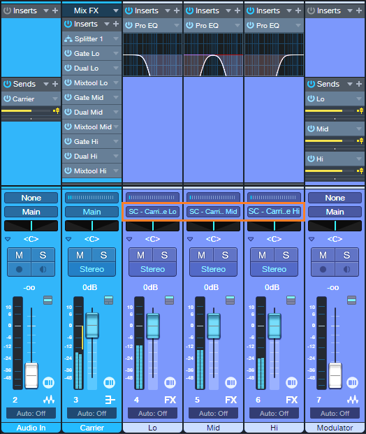
Figure 1: The blue channels are the Carrier, the violet channels are the Modulator. The Modulator bus outputs with the orange outline have been assigned to Gate sidechains in the Carrier.
4. Choose audio for the Audio In and Modulator tracks, and you’re ready to do some groove hacking. To get a feel for how this works, try a synth pad or power chord for the Carrier, and a drum loop for the Modulator.
5. The Macro Controls panel’s default settings will likely not work well with the Audio In and Modulator tracks you’re using, because the Groove Hacking effect is sensitive to levels. So, once you have the setup in place, use the Macro Controls panel to optimize the effect.
How to Use the Carrier Bus Macro Controls
Fig. 2 shows the Macro Controls for the Carrier’s FX Chain.
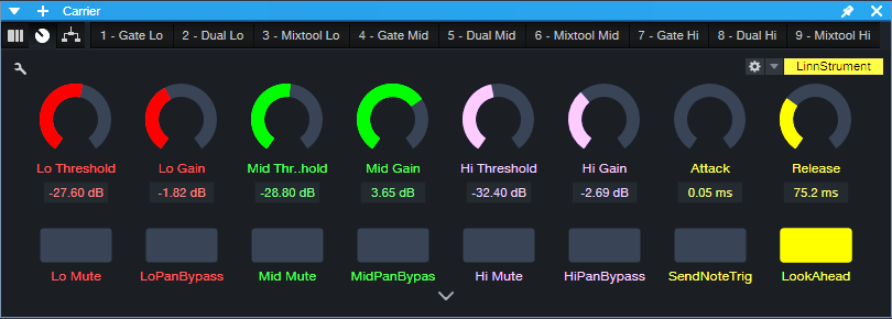
Figure 2: Controls that relate to a specific Gate have the same color. The yellow macro controls, and the LookAhead and Send Note Trig buttons, are global.
The following are per-band Gate controls:
- Threshold edits the triggering characteristics for each Gate (Lo, Mid, and Hi bands). If turned up too high, triggering won’t happen and you’ll hear no sound. If turned down too low, the sound will be on almost all the time instead of following the modulator’s rhythm.
- Gain adjusts the output level for each Gate. Use these controls to achieve the best balance among the three frequency bands.
- Mute turns off individual bands. When choosing the optimum Threshold for one band, it’s convenient to mute the other bands.
- Pan Bypass. The Lo, Mid, and Hi bands have default pan positions of center, left, and right respectively. Turn on the Pan Bypass button to center a band in the stereo field.
The following are global controls:
- Attack edits the time for the triggered sound to ramp up to its full level. Turning this up can give short “swell” effects.
- Release is important, because it determines the percussive character of the triggered sounds.
- For advanced applications beyond the scope of this tip, enabling Send Note Trig exposes the Gate note trigger outputs as MIDI inputs for Instrument tracks. Every time a Gate opens, it sends a MIDI note trigger. For example, you might want to trigger a kick drum sound every time the Lo Gate opens. The triggers default to Note C3 with a Velocity of 100. To modify the note pitch and velocity, open the FX Chain, and open the Gate whose note you want to edit.
- Leave LookAhead on. Turning it off reduces latency by 2 ms, but the tradeoff is less precise triggering.
Under the Hood: How It Works
The Carrier Section (blue channels in fig. 1) has an Audio Input channel and a bus. The Audio Input’s pre-fader Send feeds audio to the Carrier bus. The bus splits the audio into three bands, followed by gates. Triggering the gates from control signals generated by the Modulator Section (violet channels in fig. 1) processes the Carrier audio.
The Modulator Section derives the control signals:
- The Modulator audio’s channel has three pre-fader sends that feed three FX Channels.
- Each send goes to its own FX Channel.
- Each FX Channel has a Pro EQ3 that isolates a particular frequency band.
- Each FX Channel Output provides a control signal to the sidechains of the Carrier’s Gates. These control signals open and close the Gates.
The Carrier Section processes the audio it receives from the Audio In track’s pre-fader Send with the Carrier’s Extended FX Chain. Fig. 3 shows the FX Chain’s Routing Window. The splits are frequency-based, with split points at 250 Hz and 1.50 kHz. Each band goes to a series connection of a Gate, Dual Pan, and Mixtool.

Figure 3: Incoming Carrier audio feeds a frequency-based Splitter, which splits into three bands. Each of the three bands goes to a dedicated Gate, Dual Pan, and Mixtool.
Optimizing the Frequency Splits
You may need to optimize the Carrier’s Splitter frequencies, as well as the Modulator’s EQ frequencies, for the audio you want to process. In most cases, the Carrier’s Splitter bands and Modular EQ bands should be the same, and the Modulator’s frequency bands shouldn’t overlap. To do this:
- Set the Modulator’s Lo band Pro EQ3’s HC Freq to the same frequency as the Mid band Pro EQ3’s LC Freq. This is also the same frequency as the Splitter’s low frequency split.
- Set the Hi band Pro EQ3’s LC Freq to the same frequency as the Mid band Pro EQ3’s HC Freq. This is also the same frequency as the Splitter’s high frequency split.
The stages mentioned above are the only ones used in the Pro EQ3 processors. For the best separation between the bands, choose a 24 dB/octave slope. However, there are no rules! The bands can overlap, have different slopes, use a peak response for some bands, or whatever sounds best.
How to GetTips for Getting the Most Out of This Tip
- Groove Hacking pairs well with virtual instruments, especially pads. Replace the Audio In track with an Instrument track. Insert a pre-fader send in the Instrument track, and assign it to the Carrier bus.
- Adjusting the Threshold Macro Control for each band is crucial. Mute the bands whose Threshold you’re not adjusting. For further editing, the Lo, Mid, and Hi FX Channel faders can fine-tune the audio going to the Gate’s sidechain. If a band’s Gate Threshold can’t be turned down or up far enough, reduce or raise the level of its corresponding FX Channel fader respectively. Automating these faders and varying their levels can add even more variety to the sound.
- The Carrier’s pre-fader send allows for flexible mixing. With the Carrier’s channel fader down, the Audio In or Instrument track’s pre-fader send sets the mix of the Carrier in the final output. Turning up the Carrier’s channel fader mixes in the original signal feeding the Audio In (or the sound of a virtual instrument from an Instrument track).
- To mix in some of the raw Modulator sound, turn up its Channel fader.
- The Carrier bus can receive sends from multiple Channels, not just the Audio In. So, you can process multiple channels simultaneously.
- To vary the stereo placement and width of the three Carrier band’s outputs, open the FX Chain and alter the Dual Pan settings.
- Experiment with this tip early in the mixing process. You may find you don’t need as much instrumentation when one of them is blurring the line between melody and rhythm.
In the audio example, the Modulator is a drum loop from the MVP Loops – Afro Pop loop library. The Carrier is a Mai Tai preset. In the second half, a bit of the dry modulator sound fades in.
Download the Groove Hacking Track Preset here!